
I decided to fit out my Royal Enfield Bullet with an electronic points saver. I was happy to keep the points and the mechanical advance/retard mechanism – I really just wanted to take the load off the points and the capacitor.
The advantage is that the points will not wear although the heel of the breaker will wear as before. ( A smear of lithium grease is probably a good idea). The points gap is not critical, other than making sure it opens at the right point.
There is a pretty cheap module made by Vellerman but the design is awful. I was an electronic design engineer for many years and I noticed that many components can be over stressed when the engine is stationary. Although the module has a good reputation I believe this is due to the safety margins built into the components.
So as regards my design.
- Simple
- Rugged
- Low power dissipation
- Operate over a wide voltage range.
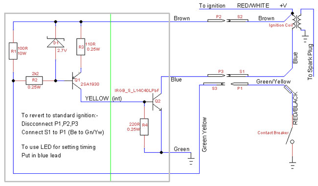
- Be able to revert to standard ignition as a back up.
Points interface
The points need a certain amount of “cleaning current”. 100-200mA seems OK (difficult to find recommendations). So with a supply under normal operation of around 15V a 100 ohm resistor to the +ve supply will give 150mA and dissipate 2.25W continuously if the points are closed.
I decided to use a 10W panel mounted resistor (R1 below).
The capacitor (or condenser)
Most articles on the web are adamant that the capacitor should be removed.
The capacitor is about 0.22uF and with a 100ohm resistor gives a time constant of 22uS. Transistor Q1 will not start to switch off until the base voltage reaches 0.7V from the positive rail. Using the formula :-
t = -CR x log(1-Vc/Vs) (log to base e)
where Vs = 15 and Vc = 14.7gives t as 67uS
So there will be around a 67uS delay between the points opening and the spark.
At 5000rpm, that’s about 2.2 degrees.
The resonant frequency of the coil with the condenser is given by
f = 1/(2*Pi*(LC)^.5))
L is around 3mH and C is around 0.22uF
This gives a resonant frequency of around 6Khz. So the first peak appears 40uS after the points open.
These calculations ignore the capacitance of the coil.
There is therefor only around 27uS difference – or less than a degree!
SO overall, the condenser could be left in or out. The difference in timing is not worth bothering about. As it now only sees 15V peak instead of around 300V and a peak current of 150mA instead of 3A, it should last forever.
Update. After building the unit, the bike ran very well with the condenser in circuit. I tried disconnecting it and, for the first time since I got the bike, it kicked back!
I can take a hint – I put it back. It was probably caused by a secondary spark as the points bounce as they close.The Time constant of the coil (L/R) is about 0.75mS. At 5000 rpm that corresponds to 22.5 degrees. I.E the engine has turned 22.5 degrees by the time the current in the coil has reached 70% of its final value.
But at starting speeds – say 1 rev per second – the current builds up in less than half a degree of engine rotation or a quarter of a degree in cam rotation.
The fast electronic switch is quite capable of switching this current off if the points bounce on closing causing a spark 20-30 degrees advanced – and kickback.
The capacitor seems to delay the spark by enough to suppress this.One lives and learns.
Further update. After around 500 miles driving then a month sitting in the garage, the bike would not start. The ammeter showed no change in current as the engine was kicked over indicating no current to the coil.
Examination revealed that the points, when closed, were not conducting. Maybe 150mA is not enough “cleaning current”.
Hang on – the points are just a switch, and now operating at around 14V and 0.14Amps so virtually no arcing. Why don’t I lubricate them like any other switch? A trawl on the web indicates that switch contacts should always be lubricated, but in distributors, only lubricating the cam is mentioned.So I have installed new points and with some dielectric grease smeared on the points themselves as well as chainsaw oil on the cam.
The points gap according to the enfield manual is 0.35-0.4mm which is 14-16 thou, which ties in with the forums. But a recent post on MBR about a rogue spark indicates that it is better to be at the lower end, so I will reset to 0.35mm.One is still living and learning – often by experiment.
Yet another update. Ater sitting in the garage for a month, the bike started first kick. That grease on the points seems to be beneficial
Coil driver
This transistor is designed for the job. At 4A it only drops about 1V so dissipation is 4W with the points closed, so a good thermal connection to the case is needed. As usual, it is the collector which is connected to the tab so an insulating washer is needed. It needs about 4V on the gate to drive it. (Q2 below).
Mid section
A mid section is needed for the simple fact that the current needs to flow through the coil driver when the points are closed. I also used this section to make the system operate over a wide voltage range.
My solution was to use a PNP transistor (Q1 below) and a zener diode to (D1) make a constant current generator. The resistor to provide the gate voltage will be a 0.25W device, derated to 30% so that’s about 85mW. At 4V that comes out as 192 Ohms. 220ohms will do which gives us 20mA (R4)
The constant current flows through the PNP. The base is anchored at 2.7V from the positive rail via the zener diode so its emitter is 2V from the rail. 100ohms ensures the correct current.
The drive for the zener diode is through a resistor which is connected to 0V via the points. It’s value is not critical. A 2.2K resistor provides a zener current of around 5mA and dissipates around 60mW.
With 6.4V total dropped across the resistors, (R3 and R4), the rest is dropped across the PNP. At 15V supply that could be 8.6V. At 20mA that is 0.17W. A power transitor is used, mainly for mechanical assembly considerations, but it also ensures that power dissipation is not an issue. I used an insulated tab one (a TO220F package) so that I didn’t have to use an insulating kit.
The transistor will continue to operate as normal down to around a 7V supply, but due to the switching characteristic of Q2, which only needs 2V to switch, it should continue to operate right down to about 4V supply. Although the coil will probably not produce much of a spark at the resulting low current.
The entire assembly only takes 170mA from 14.4V (1.7W) plus the 4W (max) dissipation in the coil driver when the points are closed. When the points are open, power dissipated is zero. The points are only closed for 10-20% of the time on a single cylinder engine so, while running, dissipation is around 1W.
Assembly
I used to be an electronic design engineer and I could pass my designs to a wireman to assemble. I am not a good, or even average, wireman so my wiring ain’t pretty. With hindsight. if I were building another (unlikely) I would use a longer box to avoid mounting components on both sides. All components were purchased from eBay.
The power resistor and the two transistors are mounted inside a metal box. The transistors are “dead bugged” i.e. screwed to the case with their legs sticking up. The other components are mounted on the resistor and transistor legs – no pcb. After testing for a few hundred miles, the box will be filled with hot melt glue.

Flying leads come from the box. To ensure the system can be reverted to standard simply and quickly. The unit is mounted in the right hand tool box. The wires come in and connect to the unit’s flying leads via crimps. I decided against a separate fuse. Any failure of a semiconductor cannot cause a short circuit. A ring connector is used on the Earth lead.

Three leads enter the toolbox from the coil. I decided to use a piece of mains cable for this. It is cheap, and I had lots anyway, and it will easily take the 300V peak voltage.
A ring connector comes from the coil positive and the points-coil lead is broken and leads added with permanent in line crimps to the connections into the tool box.
Ignition timing was checked as shown here.